Rotation Matrices in Quadcopter dynamics
-
-
Linear Algebra -
UAVs
Introduction
In robotics and aerospace engineering, rotation matrices are vital tools for translating vector coordinates from one frame of reference to another. When applied to systems like quadcopters, they enable easy transformation of vectors from the quadcopter’s body frame to an external, fixed inertial frame1.

Definition
A rotation matrix is a mathematical construct used to rotate vectors in three-dimensional space. By applying a rotation matrix, we can convert the representation of a vector from one coordinate system to another.
- For instance, a vector expressed in a quadcopter’s body frame can be translated to the inertial frame of the ground.
To better understand its significance, consider a quadcopter in flight :

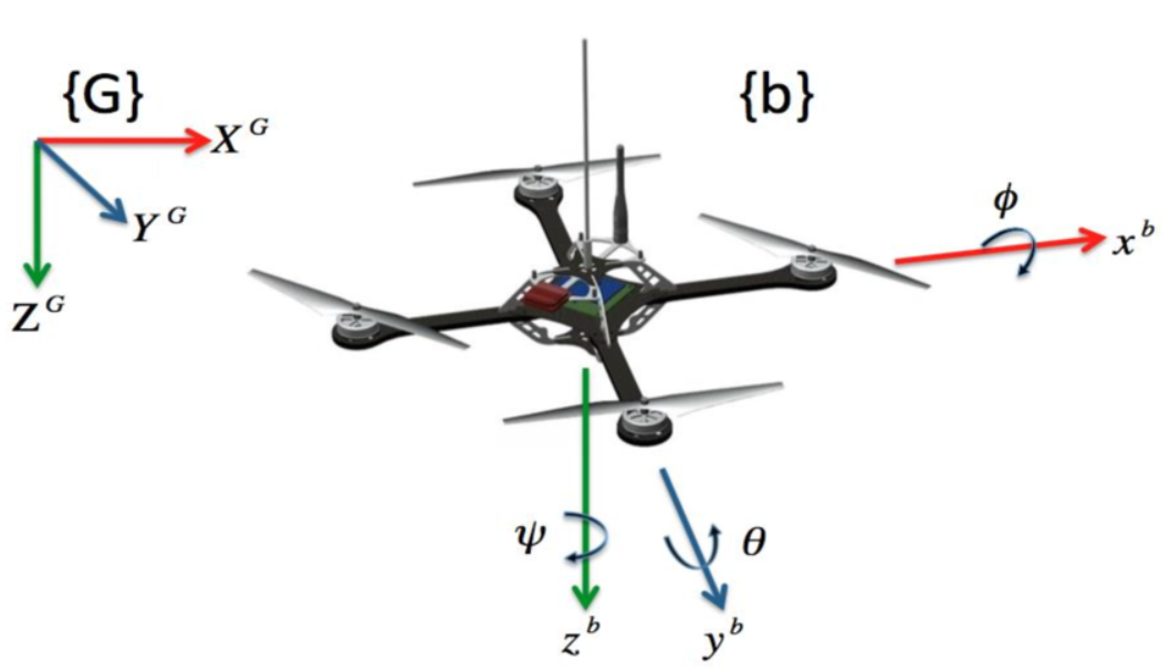
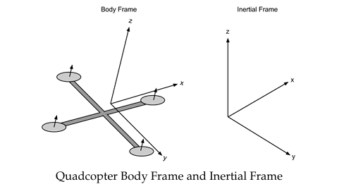
- Body Frame: This coordinate system moves and rotates with the quadcopter, with its own x, y, and z axes aligned to the craft’s orientation.
- Inertial Frame: This is a fixed coordinate system, usually defined relative to the ground, representing Earth’s x, y, and z axes.
Movement
When the quadcopter performs movements such as yaw, pitch, or roll, vectors in its body frame must be converted to the inertial frame for accurate computation of movement, orientation, and external interactions. This transformation is essential for navigation systems, trajectory planning, and understanding how the quadcopter behaves relative to the Earth.
Constructing the Rotation Matrix:
The rotation matrix 𝑅 is built using Euler angles that represent three successive rotations:
- Yaw ( 𝜓 ): Rotation around the z-axis, adjusting the direction in the horizontal plane (e.g., turning left or right).
- Pitch ( 𝜃 ): Rotation around the new y-axis, tilting the quadcopter’s nose up or down.
- Roll ( 𝜙): Rotation around the new x-axis, causing side-to-side tilting.
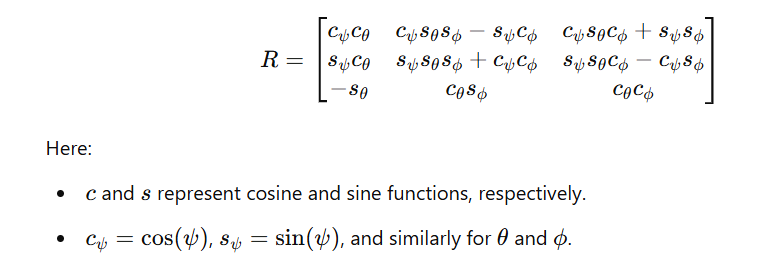
These rotations give us the full rotation matrix 𝑅:

Thus:
For a given vector x in the body frame, the corresponding vector is given by Rx in the inertial frame
Example Scenario Suppose the quadcopter tilts and rotates mid-flight. You need to know where “forward” points now from the ground’s perspective (in the inertial frame). By applying 𝑅 to a vector pointing forward in the body frame, you get a new vector showing where that direction is pointing from the ground’s view.
- This is crucial for controlling the quadcopter’s motion relative to the ground and understanding how it interacts with the environment.
Conclusion
The quadcopter’s motion involves complex kinematics where the body’s position and orientation need to be managed using the speeds of its four rotors. The relationship between body movements and world movements is defined through a rotation matrix 𝑅, which captures how the body frame’s orientation maps to the fixed inertial frame. This matrix is crucial for designing controllers that can direct the quadcopter’s movement and stabilize it in flight.
Footnotes
-
Rotation matrices transform vectors between a quadcopter’s body and external frame. ↩